Digital Combination Lock Circuit with Keypad and LCD Circuit Diagram
Digital Combination Lock Circuit with Keypad and LCD Circuit Diagram This is a door lock security system made with Arduino. Door Lock System with Arduino. interfacing_keypad_with_arduino_8xDFWS5uS3.JPG. lcd_with_arduino_ZHuuxD17fT.JPG. lcd_with_arduino_ZHuuxD17fT.JPG. CIRCUIT DIAGRAMS. CIRCUIT DIAGRAMS. Comments. Only logged in users can leave comments.
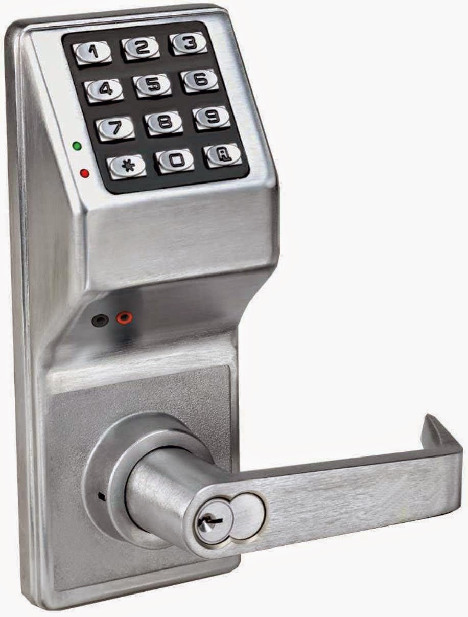
555 Timer electronic Door lock; RFID Door lock system using Arduino; Before building our password door locking project, first, we need to collect the required components and then go ahead and follow the step by step building process. Arduino Code for Digital Keypad Door Lock. The design files are also shown in the picture below. In this instructable, I will be showing you how to create an Arduino controlled and activated safe lock mechanism. The system functions the same way a normal safe mechanism would, you enter a 4 digit code onto the keypad attached to the Arduino, if you enter the correct code, the Arduino will then send a signal to the servo motor to start In this tutorial, we will show users how a digital code lock system works in an Arduino Interface. By the end of this tutorial you will be able to : Set up a digital code lock with Zio and basic 12 keys keypad; Be able to interface with Arduino IDE to program Zio with keypad; Create a program that asks users to enter a six-digit password to unlock
Password based door lock system using Keypad part 2 Circuit Diagram
𝗩𝗶𝗱𝗲𝗼 𝗗𝗲𝘀𝗰𝗿𝗶𝗽𝘁𝗶𝗼𝗻:In this project, we will make a Password-Based Door Lock Security System using Arduino, a keypad, a servo motor, an LCD, an
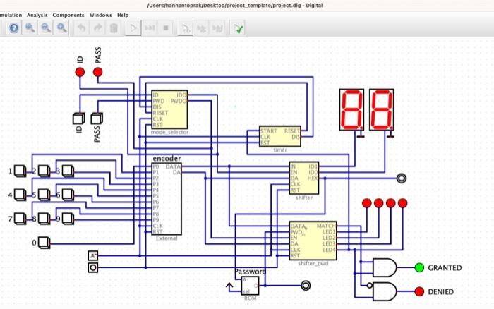
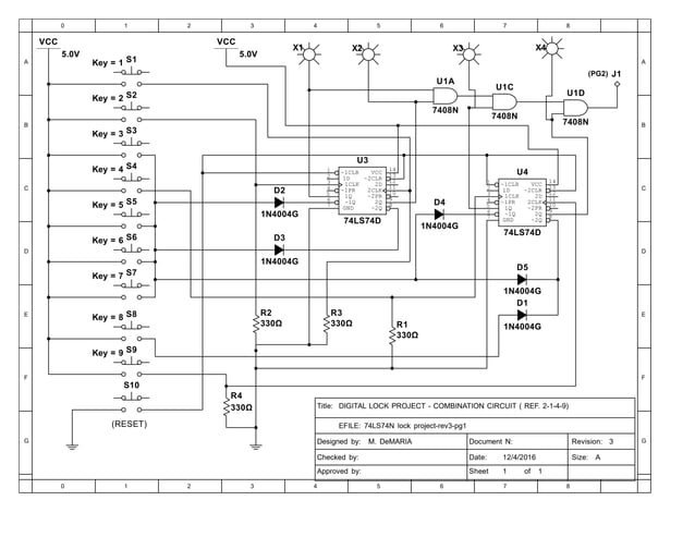
The numbers that will represent each button are from 1-9. The keypad will have outputs in a 4-bit format. For example, when you press the '7' button then the output from OR gates will be '0111'. Construct the keypad by following the attached picture above. After the keypad is constructed, connect the outputs from the OR gates into 4043 IC. Learn how to make a door lock system using password with keypad and Solenoid lock. When the door is unlocked by a correct password, It keeps the door unlocked for 20 seconds, and then automatically locks the door again. The Arduino code supports multiple passwords. The detail instruction, code, wiring diagram, video tutorial, line-by-line code explanation are provided to help you quickly get Tinkercad is a free web app for 3D design, electronics, and coding. We're the ideal introduction to Autodesk, a global leader in design and make technology. Follow Us
